Still under construction
Commands that still require documentation: 2
■ Contents
- 1. Overview
- 2. Syntax
- 3. Preprocessing
- 4. The Options namespace
- 5. The Route namespace
- 6. The Train namespace
- 7. The Structure namespace
- 8. The Texture namespace
- 9. The Cycle namespace
- 10. The Signal namespace
- 11. The Track namespace
■ 1. Overview
A CSV route allows to create a route in a text file.
The file is a plain text file encoded in any arbitrary encoding, however, UTF-8 with a byte order mark is the preferred choice. The parsing model for numbers is Loose (unless otherwise stated), however, you are encouraged to produce Strict output nonetheless. The file is required to be located inside any folder whose current or parent folder includes the Railway and Train folders. The file name is arbitrary, but must have the extension .csv. The file is interpreted on a per-line basis, from top to bottom, where each line is split into expressions, which are interpreted from left to right.
The route file consists of a series of commands to define the objects which are used throughout the route (Structure namespace). Additional properties for the route, for the default train to be used and for the background images to be used can also be defined. At last, the route file will contain instructions from the Track namespace. Here, track positions (usually in meters) are used to define when the track should curve, when stations are to be placed, when a wall should start and end, and so on. Generally speaking, instructions from the Track namespace should be used after using instructions from any of the other namespaces.
The format assumes an implicit rail 0 which cannot be explicitly started or ended. Instead, it is present from the beginning of the route to the end, and it marks the rail the player’s train drives on. All other rails in the CSV format are purely visual and have no functional purpose.
Geometrically, you can curve and pitch the implicit rail 0, while all other rails are defined relative to rail 0 and follow rail 0 into curves and pitch changes. Unless overridden, the file format is built around a fixed block size of 25 meters length, and it is only possible for certain commands to be used on 25 meter block boundaries. The placement of objects always assumes a non-curved coordinate system which connects blocks linearly.
➟ See also the quick reference for the CSV route…
■ 2. Syntax
For each line in the file, white spaces at the beginning and the end of that line are ignored. Then, lines are split into individual expressions, separated by commas (U+002C). Thus, each line is of the following form:
Expression1, Expression2, Expression3, …, Expressionn
In turn, each expression can be of any of the following forms:
● Comments
A comment is completely ignored by the parser. To form a comment, the expression must begin with a semicolon (U+003B).
● Track positions and lengths
Position
A non-negative strict floating-point number corresponding to a track position. All subsequent commands from the Track namespace are associated to this track position.
Part1:Part2:…:Partn
This is a more complex way of specifying track positions for use in conjunction with Options.UnitOfLength. Each of the Parti is a strict floating-point number. Part1 will be multiplied with Factor1, Part2 with Factor2, and so on, then all products are added together to form the final track position. This track position must be non-negative. The parts are separated by colons (U+003A). Please consult Options.UnitOfLength for further information on how to define the factors.
Wherever arguments in commands represent lengths, they can also be entered using the colon notation. These cases are highlighted in green in the following.
When n units are defined via Options.UnitOfLength, but fewer parameters are given using the colon notation, the parameters are right-associative, meaning, the parameters on the left are those which are skipped. Therefore, each of the following lengths are equivalent: 0:0:2, 0:2, and 2.
● Commands
Commands without arguments:
NameOfTheCommand
Commands with arguments:
NameOfTheCommand Argument1;Argument2;Argument3;…;Argumentn
NameOfTheCommand(Argument1;Argument2;Argument3;…;Argumentn)
Rules:
NameOfTheCommand is case-insensitive. Indices and arguments are separated by semicolons (U+003B). White spaces around NameOfTheCommand and any of the indices and arguments are ignored. White spaces surrounding any of the parentheses are also ignored.
If indices are used, these are enclosed by opening parentheses (U+0028) and closing parentheses (U+0029). At least one argument, or a Suffix is mandatory when using indices.
There are two variations on how to encode arguments. Except for the $-directives ($Chr, $Rnd, $Sub, …), you can freely choose which variant to use. Variant 1: The first argument is separated from the command, indices or Suffix by at least one space (U+0020). Variant two: The arguments are enclosed by opening parentheses (U+0028) and closing parentheses (U+0029). In the latter case, Suffix is mandatory when used in conjunction with indices. White spaces surrounding any of the parentheses are ignored.
Please note that in some commands, Suffix is mandatory regardless of the style you use to encode arguments. In the following, Suffix will be bolded when it is mandatory, and grayed when it is optional.
● The With statement
With Prefix
All subsequent commands that start with a period (U+002E) are prepended by Prefix. For example:
| ▶ |
With Route |
Is equivalent to:
| ▶ |
Route.Gauge 1435 |
■ 3. Preprocessing
Before any of the commands in the route file are actually interpreted, the expressions are preprocessed. The first thing done is to replace any occurrences of the $-directives within an expression from right to left. The $Chr, $Rnd and $Sub directives may be nested in any way, while $Include, $If, $Else and $EndIf must not appear inside another directive.
The syntax for the $-directives cannot be freely chosen, but must adhere to the forms presented below.
$Include(File)
$Include(File:TrackPositionOffset)
$Include(File1; Weight1; File2; Weight2; …)
Filei: A file to include of the same format (CSV/RW) as the main file.
Weighti: A positive floating-point number giving a probability weight for the corresponding file.
This directive chooses randomly from the specified files based on their associated probabilities and includes the content from one selected file into the main file. The content is copied into the place of the $Include directive, meaning that you need to take care of track positions and the last used With statement, for example. If the last weight in the argument sequence is omitted, it is treated as 1.
The $Include directive is useful for splitting up a large file into smaller files, for sharing common sections of code between multiple routes, and for choosing randomly from a larger block of code. Please note that the included files may themselves include other files, but you need to make sure that there are no circular dependencies, e.g. file A including file B, and file B including file A, etc. You should use a file extension different from .csv for included files so that users cannot accidentally select them in the main menu (except where this is desired).
If any of the Filei is followed by :TrackPositionOffset, then all expressions in the included file are offset by the specified track position in meters. For example, $Include(stations.include:2000) shifts all track positions in the part.include file by 2000 meters before including them. It is important to understand that “track positions” are not actually understood until after the $-directives have been processed, so all expressions in the included file are simply flagged to be offset later should they form track positions then. This means that if the included file contains expressions such as 1$Rnd(2;8)00, these are offset, too, even though at this stage, they do not form track positions yet.
The track position offset feature is only available in the development release 1.2.11 and above.
$Chr(Ascii)
Ascii: An integer in the range from 20 to 127, or 10 or 13, corresponding to an ASCII character of the same code.
This directive is replaced by the ASCII character represented by Ascii. This is useful if you want to include characters that are part of syntax rules or would be stripped away. A list of relevant characters:
| Code | Meaning | Character |
|---|---|---|
| 10 | Newline | newline |
| 13 | Newline | newline |
| 20 | Space | space |
| 40 | Opening parentheses | ( |
| 41 | Closing parentheses | ) |
| 44 | Comma | , |
| 59 | Semicolon | ; |
The sequence $Chr(13)$Chr(10) is handled as a single newline. Inserting $Chr(59) can be interpreted as a comment starter or as an argument separator, depending on where it is used.
$Rnd(Start; End)
Start: An integer representing the lower bound.
End: An integer representing the upper bound.
This directive is replaced by a random integer in the range from Start to End. It is useful to add randomness to a route.
| Example for the use of the $Rnd directive: | |
| ▶ |
10$Rnd(3;5)0, Track.FreeObj 0; 1 |
| Possible outcome from the previous example is exactly one of these lines: | |
| ▶ |
1030, Track.FreeObj 0; 1 |
$Sub(Index) = Expression
Index: A non-negative integer representing the index of a variable.
Expression: The expression to store in the variable.
This directive should only appear as a single expression. It is used to assign Expression to a variable identified by Index. The whole $Sub directive is replaced by an empty string once the assignment is done. It is useful for storing values obtained by the $Rnd directive in order to reuse the same randomly-generated value. See the following definition of the $Sub(Index) directive for examples.
Implementation note
While it is also possible to store non-numeric strings, it is not possible to include commas via $Chr(44) and have them work as a statement separator. However, it is possible to store a semicolon as the first character via $Chr(59) and have it work as a comment. For conditional expressions, you should use $Include or $If, though.
$Sub(Index)
Index: A non-negative integer representing the index of the variable to retrieve.
This directive is replaced by the content of the variable Index. The variable must have been assigned prior to retrieving it.
| Example for the use of the $Sub(Index)=Value and $Sub(Index) directives: | |
| ▶ |
$Sub(0) = $Rnd(3; 5) |
In the previous example, all three Track.FreeObj commands are guaranteed to use the same randomly-generated value in order to place a free object on the same rail. If you inserted the $Rnd(3;5) directive in each of the three lines individually, the objects could be placed on different rails each time.
$If(Condition)
Condition: A number that represents false if zero, and true otherwise.
The $If directive allows to only process subsequent expressions if the specified condition evaluates to true (any non-zero number). $If must be followed by $EndIf in any subsequent expression. Optionally, an $Else directive may appear between $If and $EndIf.
$Else()
The $Else directive allows to only process subsequent expressions if the condition in the preceding $If evaluated to false (zero).
$EndIf()
The $EndIf directive marks the end of an $If block that was started previously.
| Example of $If, $Else and $EndIf | |
| ▶ |
$Sub(1) = 0 |
| Another example of $If, $Else and $EndIf | |
| ▶ |
With Track |
It is possible to nest $If blocks. If you place $If/$Else/$EndIf on separate lines, you may want to employ indentation to improve readability of the block structure (as in the first example).
Finally, after the $-directives have been processed, all expressions in the route file are sorted according to their associated track positions.
| Example of a partial route file: | |
| ▶ |
1000, Track.FreeObj 0; 23 |
| Preprocessing the $Rnd directive (assuming 3 is produced): | |
| ▶ |
1000, Track.FreeObj 0; 23 |
| Sorting by associated track positions: | |
| ▶ |
1000, Track.FreeObj 0; 23 |
■ 4. The Options namespace
Commands from this namespace provide generic options that affect the way other commands are processed. You should make use of commands from this namespace before making use of commands from other namespaces.
Options.UnitOfLength FactorInMeters1; FactorInMeters2; FactorInMeters3; …; FactorInMetersn
FactorInMetersi: A floating-point number representing how many meters the desired unit has. The default value is 1 for FactorInMeters1, and 0 for all others.
This command can be used to specify the unit of length to be used in other commands. When entering a generic track position of the form Part1:Part2:…:Partn, each of the Parti will be multiplied with the corresponding FactorInMetersi, then all of these products are added to form a single track position represented in meters. Ideally, you should set the block length to an integer multiple of any of the units you use via Options.BlockLength.
Examples of conversion factors:
| Desired unit | Conversion factor |
|---|---|
| mile | 1609.344 |
| chain | 20.1168 |
| meter | 1 |
| yard | 0.9144 |
| foot | 0.3048 |
In the following, all arguments of all commands are highlighted in green whenever they are affected by Options.UnitOfLength.
Options.UnitOfSpeed FactorInKmph
FactorInKmph: A floating-point number representing how many kilometers per hour the desired unit has. The default value is 1.
This command can be used to specify the unit of speed to be used in other commands. Examples of conversion factors:
| Desired unit | Conversion factor |
|---|---|
| meters/second | 3.6 |
| miles/hour | 1.609344 |
| kilometers/hour | 1 |
In the following, all arguments of all commands are highlighted in blue whenever they are affected by Options.UnitOfSpeed.
Options.BlockLength Length
Length: A positive floating-point number representing the length of a block, by default measured in meters. The default is 25 meters.
This command can be used to specify the length of a block. This is an overall setting and cannot be changed in the middle of the route. Length is only expressed in the unit specified by Options.UnitOfLength if Options.UnitOfLength is used before Options.BlockLength.
Options.ObjectVisibility Mode
Mode: The mode determining how objects appear and disappear. The default value is 0 (legacy).
▸ Available options for Mode:
0: Legacy: An object is made invisible as soon as the end of the block which it resides in has been passed by the camera. This does not work well when turning the camera around. Self-intersecting track (e.g. loops) is not possible.
1: Track-based: An object is made invisible as soon as its end has been passed by the camera. This is measured in track positions. Self-intersecting track (e.g. loops) is not possible.
Options.SectionBehavior Mode
Mode: The mode determining how the Track.Section command is processed. The default value is 0 (default)
▸ Available options for Mode:
0: Default: In Track.Section Aspect0; Aspect1; …; Aspectn, any of the Aspecti refer to the aspect the section should have if i following sections are clear.
1: Simplified: In Track.Section Aspect0; Aspect1; …; Aspectn, the section bears the smallest aspect which is higher than that of the following section.
Options.CantBehavior Mode
Mode: The mode determining how cant in the Track.Curve command is processed. The default is 0 (unsigned).
▸ Available options for Mode:
0: Unsigned: The CantInMillimeters parameter in Track.Curve is unsigned, i.e. the sign is ignored and the superelevation is always towards the curve center (inward). Cant cannot be applied on straight track.
1: Signed: The CantInMillimeters parameter in Track.Curve is signed, i.e. negative values bank outward and positive ones inward on curved track. Cant can be applied on straight track, where negative values bank toward the left and positive ones toward the right.
Options.FogBehavior Mode
Mode: The mode determining how the Track.Fog command is processed. The default value is 0 (Block-based).
▸ Available options for Mode:
0: Block-based: Fog color and ranges are interpolated from the beginning of the block where Track.Fog is used with the old settings to the end of the block with the new settings.
1: Interpolated: Fog color and ranges are interpolated between adjacent Track.Fog commands. This behavior mimicks Track.Brightness.
Options.CompatibleTransparencyMode Mode
Mode: The mode determining how transparencies are processed in BVE2/ BVE4 objects which use a restricted color pallet. This may be used on a per-route basis to override the value set in ‘Options’.
▸ Available options for Mode:
0: Off: Colors are matched specifically. If the specified transparent color does not exist within the color pallet, no transparency will be added.
1: On: Fuzzy matching. If the texture uses a restricted color pallet, the transparent color will be clamped to the nearest available color in the pallet.
Options.EnableBveTsHacks Mode
Mode: The mode determining whether various hacks are applied in order to fix BVE2 / BVE4 content. This may be used on a per-route basis to override the value set in ‘Options’.
▸ Available options for Mode:
0: Off: Hacks are disabled.
1: On: Hacks are enabled.
■ 5. The Route namespace
Commands from this namespace define general properties of the route.
Route.Comment Text
Text: The route comments which appear in the route selection dialog.
You need to use $Chr directives if you want to include newlines, commas and the like in the text.
Route.Image File
File: The file name of the image which appears in the route selection dialog, relative to the route’s folder.
Route.Timetable Text
Text: The text which appears at the top of the default timetable.
You need to use $Chr directives if you want to include newlines, commas and the like in the text.
Route.Change Mode
Mode: The mode for the train’s safety system to start in. The default value is implementation-specific.
▸ Available options for Mode:
-1: The safety system is activated and the service brakes are applied.
0: The safety system is activated and the emergency brakes are applied.
1: The safety system is deactivated and the emergency brakes are applied.
Route.Gauge ValueInMillimeters
ValueInMillimeters: A floating-point number representing the rail gauge, measured in millimeters (0.001 meters). The default value is 1435.
Train.Gauge is the same as Route.Gauge.
Route.Signal(AspectIndex).Set Speed
AspectIndex: A non-negative integer representing the signal aspect. The aspect 0 corresponds to red.
Speed: A non-negative floating-point number representing the allowed speed for this aspect, by default measured in kilometers per hour (km/h).
Use this command to associate speed limits to signal aspects. Aspect 0 represents a red signal, higher values represent more permissive aspects. The default values (for the included Japanese signals) are:
| Index | Aspect | Speed |
|---|---|---|
| 0 | ● | 0 km/h |
| 1 | ●● | 25 km/h |
| 2 | ● | 55 km/h |
| 3 | ●● | 75 km/h |
| 4 | ● | unlimited |
| 5 | ●● | unlimited |
Route.RunInterval Interval0; Interval1; …; Intervaln-1
Intervali: A floating-point number representing the time interval between the player’s train’s timetable and that of another train to be created, measured in seconds. Positive values indicate an earlier train, negative numbers a later train.
This command creates one or more preceding or following trains. These other trains are visible, fully operational, and use the same train as the player has. The other trains follow the same schedule as the player does, but are offset in time by Intervali. Via the Track.Sta command, you can also define stations where only the player or only the other trains should stop. Follow-up trains only appear once the section they are placed in has been cleared by other trains, but the player’s train is introduced regardless of the current signalling section’s state. Therefore, you should make sure that other trains have cleared the area where the player’s train will appear when the scenario begins.
Route.RunInterval is the same as Train.Interval.
Route.AccelerationDueToGravity Value
Value: A positive floating-point number representing the acceleration due to gravity in meters per second squared (m/s²). The default value is 9.80665.
Route.Elevation Height
Height: A floating-point number representing the initial height above sea level, by default measured in meters (m). The default value is 0.
Route.Temperature ValueInCelsius
Value: A floating-point number representing the initial temperature in Celsius. The default value is 20.
Route.Pressure ValueInKPa
ValueInKPa: A positive floating-point number representing the initial air pressure in kPa (1000 Pascal). The default value is 101.325.
Route.DisplaySpeed Unit; ConversionFactor
Unit: The textual units in which speed-related messages are to be displayed. ConversionFactor: The conversion factor between km/h and your custom unit of speed. For mph, this is 0.621371.
This command allows speed related messages (overspeed etc.) to be displayed in a custom unit, for example mph.
Route.LoadingScreen Image
Image: A path to a supported image file.
This command allows a custom image to be set as the loading screen background.
Route.StartTime Time
Time: The time at which the simulation is to start.
This command allows the start time of the simulation to be set.
If this is not set or is invalid, the simulation will start at the arrival time set at the first station.
Route.DynamicLight Dynamic.XML
Dynamic.XML: A path to a Dynamic Lighting definition XML file.
This command may be used as an alternative to the Route.AmbientLight , Route.DirectionalLight and Route.LightDirection commands.
It allows the lighting to be varied using a time-based model, and is described fully on the following page:
Route.AmbientLight RedValue; GreenValue; BlueValue
RedValue: An integer ranging from 0 to 255 representing the red component of the ambient light. The default value is 160.
GreenValue: An integer ranging from 0 to 255 representing the green component of the ambient light. The default value is 160.
BlueValue: An integer ranging from 0 to 255 representing the blue component of the ambient light. The default value is 160.
This command defines the ambient light color to be used. All polygons in the scene are illuminated by the ambient light regardless of the light direction.
Route.DirectionalLight RedValue; GreenValue; BlueValue
RedValue: An integer ranging from 0 to 255 representing the red component of the directional light. The default value is 160.
GreenValue: An integer ranging from 0 to 255 representing the green component of the directional light. The default value is 160.
BlueValue: An integer ranging from 0 to 255 representing the blue component of the directional light. The default value is 160.
This command defines the directional light to be used. The polygons in the scene are only fully illuminated by the directional light if the light direction points at the front faces. If pointing at back faces, no light is contributed. Route.LightDirection should be set to specify the light direction.
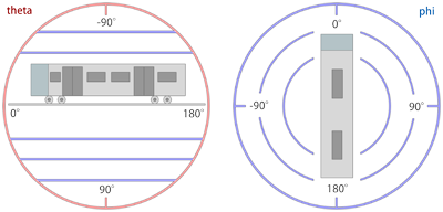
Route.LightDirection Theta; Phi
Theta: A floating-point number representing the angle in degrees which controls the pitch of the light direction. The default value is 60.
Phi: A floating-point number representing the angle in degrees which controls the planar rotation of the light direction. The default value is about -26.57.
This command defines the initial light direction for track position 0. This is the direction the light shines at, meaning the opposite direction the sun is located at. First, Theta determines the pitch. A value of 90 represents a downward direction, while a value of -90 represents an upward direction. With those extremes, the value of Phi is irrelevant. A value of 0 for Theta represents a forward direction originating at the horizon behind. Once the pitch is defined by Theta, Phi determines the rotation in the plane. A value of 0 does not rotate, a value of 90 rotates the direction to the right and a value of -90 rotates to the left. A backward direction can be both obtained by setting Theta and Phi to 180 and 0 or to 0 and 180, respectively. Values in-between allow for more precise control of the exact light direction.
| Converting a spherical direction (theta,phi) into a cartesian direction (x,y,z): | |
| ƒ |
x = cos(theta) * sin(phi) |
| Converting a cartesian direction (x,y,z) into a spherical direction (theta,phi) for y²≠1: | |
| ƒ |
theta = -arctan(y/sqrt(x2+z2)) |
| Converting a cartesian direction (x,y,z) into a spherical direction (theta,phi) for y²=1: | |
| ƒ |
theta = -y * pi/2 |
In the formulas above, cos(x) represents the cosine, sin(x) the sine, arctan(x) the inverse tangent, arctan(x,y) the two-argument inverse tangent and sqrt(x) the square root. The formulas can be used to convert between spherical and cartesian coordinates if working with either one seems more intuitive than working with the other one. The formulas also serve as the official documentation on how the light direction is mathematically defined (using radians for the trigonometric functions).
Route.InitialViewpoint Value
Value: An integer defining the initial camera viewpoint mode. The following values are valid:
0 : The camera will be placed in the cab. (Default)
1 : The camera will be placed in ‘Track Camera’ mode.
2 : The camera will be placed in ‘Flyby Camera’ mode.
3 : The camera will be placed in ‘Flyby Zooming Camera’ mode.
This command allows the route developer to place the initial camera in one of the alternate camera modes.
Route.DeveloperID
This command is ignored by openBVE.
■ 6. The Train namespace
Commands from this namespace define route-train associations.
Train.Folder FolderName
Train.File FolderName
FolderName: The folder name of the default train to use on this route.
Train.Run(RailTypeIndex).Set RunSoundIndex
Train.Rail(RailTypeIndex).Set RunSoundIndex
RailTypeIndex: A non-negative integer representing the rail type as defined via Structure.Rail and used via Track.RailType.
RunSoundIndex: A non-negative integer representing the train’s run sound to associate to the rail type.
The train developer provides a repertoire of different run sounds. Use this command to associate these run sounds to the rail types you use in your route. In order for the correct run sounds to be played on any of your rail types, you need to coordinate your efforts with the train developer. Please see the page about standards for further information.
Train.Flange(RailTypeIndex).Set FlangeSoundIndex
RailTypeIndex: A non-negative integer representing the rail type as defined via Structure.Rail and used via Track.RailType.
RunSoundIndex: A non-negative integer representing the train’s flange sound to associate to the rail type.
The train developer provides a repertoire of different flange sounds. Use this command to associate these flange sounds to the rail types you use in your route. In order for the correct flange sounds to be played on any of your rail types, you need to coordinate your efforts with the train developer. Please see the page about standards for further information.
Train.Timetable(TimetableIndex).Day.Load FileName
TimetableIndex: A non-negative integer representing the timetable index.
FileName: The file name for the daytime version of the timetable, relative to the train’s folder (1st choice), or relative to the Object folder (2nd choice).
Use this command to load daytime versions of the timetable. Which timetable index to show starting with a particular station can be set in Track.Sta commands.
Train.Timetable(TimetableIndex).Night.Load FileName
TimetableIndex: A non-negative integer representing the timetable index.
FileName: The file name for the daytime version of the timetable, relative to the train’s folder (1st choice), or relative to the Object folder (2nd choice).
Use this command to load nighttime versions of the timetable. Which timetable index to show starting with a particular station can be set in Track.Sta commands.
Train.Gauge ValueInMillimeters
ValueInMillimeters: A floating-point number representing the rail gauge, measured in millimeters (0.001 meters). The default value is 1435.
Train.Gauge is the same as Route.Gauge.
Train.Interval Interval0; Interval1; …; Intervaln-1
ValueInSeconds: A floating-point number representing the time interval between the player’s train and the preceding train, measured in seconds. The default value is 0.
Train.ValueInSeconds is the same as Route.RunInterval.
Train.Velocity Speed
Speed: A positive floating-point number representing the maximum speed the preceding trains may travel at, by default measured in kilometers per hour, or 0 for infinite speed. The default value is 0.
This command defines the maximum speed limit the preceding trains may travel at. The actual speed limit may be reduced by Track.Limit commands. The player’s train is unaffected by this setting and may travel up to the limits defined by Track.Limit.
Train.Acceleration
This command is ignored by openBVE.
Train.Station
This command is ignored by openBVE.
■ 7. The Structure namespace
The commands in the Structure namespace define which objects to use in other commands. Generally, commands like Track.Rail, Track.FreeObj and so on create objects referenced by a StructureIndex. This StructureIndex is specific to that command, so you can define a set of objects specific to Track.Rail, Track.FreeObj and so on.
The general syntax for commands in the Structure namespace is:
Structure.Command(StructureIndex).Load FileName
StructureIndex is a non-negative integer. FileName is the object file to load, relative to the Object folder. Command is any of the following commands:
| Command: | Remarks |
|---|---|
| Ground | Defines objects for Cycle.Ground and Track.Ground. |
| Rail | Defines objects for Track.Rail, Track.RailStart and Track.RailType. |
| WallL | Defines left objects for Track.Wall. |
| WallR | Defines right objects for Track.Wall. |
| DikeL | Defines left objects for Track.Dike. |
| DikeR | Defines right objects for Track.Dike. |
| FormL | Defines left platforms edges for Track.Form. |
| FormR | Defines right platforms edges for Track.Form. |
| FormCL | Defines transformable left platforms for Track.Form. No ANIMATED objects supported. |
| FormCR | Defines transformable right platforms for Track.Form. No ANIMATED objects supported. |
| RoofL | Defines left roof edges for Track.Form. |
| RoofR | Defines right roof edges for Track.Form. |
| RoofCL | Defines transformable left roofs for Track.Form. No ANIMATED objects supported. |
| RoofCR | Defines transformable right roofs for Track.Form. No ANIMATED objects supported. |
| CrackL | Defines transformable left objects for Track.Crack. No ANIMATED objects supported. |
| CrackR | Defines transformable right objects for Track.Crack. No ANIMATED objects supported. |
| FreeObj | Defines objects for Track.FreeObj. |
| Beacon | Defines objects for Track.Beacon. |
Generally, supported objects are B3D, CSV, X and ANIMATED. However, the FormCL, FormCR, RoofCL, RoofCR, CrackL and CrackR commands only accept B3D, CSV and X objects.
➟ More information about forms, roofs and cracks…
Additionally, there is the Structure.Pole command, which has a slightly different syntax:
Structure.Pole(NumberOfAdditionalRails; PoleStructureIndex).Load FileName
NumberOfAdditionalRails: An non-negative integer representing the number of additional rails covered by the pole. 0 creates a pole for one rail, 1 for two rails, etc.
PoleStructureIndex: A non-negative integer representing the pole structure index.
FileName: The object file to load, relative to the Object folder.
Please note that all objects but the FreeObj are inserted at the beginning of a block and should thus extend from 0 to BlockLength (by default 25m) on the z-axis. For further information on usage, see the respective commands from the Track namespace.
■ 8. The Texture namespace
Commands from this namespace define which background images to use and how they are aligned.
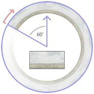
The background image is displayed as a cylindric wall around the camera whose start (viewed from above) is 60 degrees to the left of the initial forward direction (at the 10 o’clock position). From there, the background image wraps clock-wise around the cylinder with a repetition count specified via Texture.Background(BackgroundTextureIndex).X, which by default creates 6 repetitions in a full circle.
The upper 3⁄4 of the image is displayed above the horizon, while the lower 1⁄4 is displayed below the horizon. Via Texture.Background(BackgroundTextureIndex).Aspect, you can choose whether to have a fixed cylinder height or to preserve the aspect ratio of the texture. If the image should have a fixed height, the cylinder has a height of 1⁄2 its radius, which corresponds to about 20 degree inclination to the top of the image, and about -7 degrees to the bottom of the image. If the aspect ratio of the image is preserved, this takes not only the width and height of the image into account, but also the repetition count.
Regardless of the repetition count you chose, you should make sure that the left and right edges of the textures fit seamlessly together. Please also take into account that top and bottom caps are created which sample from the top and bottom 10% of the image. You should avoid mountain peaks and similar extremes in the top 10% of the image in order for such extremes to not leak into the top cap.
The image loaded into Texture.Background(0) is displayed at the beginning of the route, unless a Track.Back command at the beginning of the route requests a different image.
As an alternative Dynamic or Object based backgrounds may be used. The implementation of these is described upon this page:
Dynamic & Object Based Backgrounds
Texture.Background(BackgroundTextureIndex).Load FileName
FileName: The texture file to load, relative to the Object folder.
This command loads a background image to be later used by Track.Back.
If a dynamic or object based background is to be used, this must instead point to the appropriate XML file.
Texture.Background(BackgroundTextureIndex).X RepetitionCount
RepetitionCount: The number of times the background image is repeated in a full circle. The default value is 6.
Ignored if using a dynamic or object based background.
Texture.Background(BackgroundTextureIndex).Aspect Mode
Mode: The mode of aspect ratio handling to use. The default value is 0 (fixed).
▸ Options for Mode:
0: Fixed: Use a fixed height for the cylinder.
1: Aspect: Preserve the aspect ratio of the image.
Ignored if using a dynamic or object based background.
■ 9. The Cycle namespace
Cycle.Ground(GroundStructureIndex).Params GroundStructureIndex0; GroundStructureIndex1; GroundStructureIndex2; …; GroundStructureIndexn-1
GroundStructureIndex: A non-negative integer indicating the ground structure index for which a cycle is to be defined.
GroundStructureIndexi: A non-negative integer indicating a ground structure that has been previously loaded via Structure.Ground.
When usually using Track.Ground(GroundStructureIndex), the same ground structure object will be repeatedly placed in every block. Via Cycle.Ground, you can override this behavior and automatically cycle through a series of different objects when using Track.Ground(GroundStructureIndex). The cycle repeats indefinitely, where GroundStructureIndex0 starts at track position 0. Technically, the i in GroundStructureIndexi chosen for a particular track position p is Mod[p / BlockLength, n].
Cycle.Rail(RailStructureIndex).Params RailStructureIndex0; RailStructureIndex1; RailStructureIndex2; …; RailStructureIndexn-1
RailStructureIndex: A non-negative integer indicating the rail structure index for which a cycle is to be defined.
RailStructureIndexi: A non-negative integer indicating a rail structure that has been previously loaded via Structure.Rail.
Consider the following definition:
| ▶ |
With Structure |
The following two codes will produce the same output:
| ▶ |
With Track |
| ▶ |
With Cycle |
■ 10. The Signal namespace
Commands from this namespace define custom signals.
Signal(SignalIndex).Load AnimatedObjectFile
SignalIndex: A non-negative integer representing the signal index.
AnimatedObjectFile: A reference to an animated object file, relative to the Object folder.
Use this command to load signals directly from animated objects. The SignalIndex can be later referenced in Track.SigF commands to place the signal.
Signal(SignalIndex).Load SignalFileWithoutExtension; GlowFileWithoutExtension
SignalIndex: A non-negative integer representing the signal index.
SignalFileWithoutExtension: A reference to a B3D/CSV/X object file representing the signal, relative to the Object folder, but without the file extension. Is required to be specified.
GlowFileWithoutExtension: An optional reference to a B3D/CSV/X object file representing the distance glow, relative to the Object folder, but without the file extension.
Use this command to load signals from a series of individual textures applied onto a common object. openBVE looks for X, CSV and B3D objects in this exact order. Textures are required to have the same name as the signal or glow, plus a non-negative aspect index, plus a file extension for textures. The SignalIndex can be later referenced in Track.SigF commands to place the signal.
For the SignalFileWithoutExtension, there should be the following files present (example):
SignalFileWithoutExtension.x
SignalFileWithoutExtension0.bmp
SignalFileWithoutExtension1.bmp
SignalFileWithoutExtension2.bmp
SignalFileWithoutExtensionn.bmp
The aspect indices from 0 through n represent successively more permissive aspects, where 0 is red. The built-in signals, for example, use the indices 0 (●), 1 (●●), 2 (●), 3 (●●), 4 (●) and 5 (●●). You can use as many as required.
All faces in the object will be applied the currently active aspect texture. This means that you cannot use any other texture in the object, but still have to assign texture coordinates appropriately. For the glow object, the above rules also apply. The glow object is usually a rectangle placed clearly in front of the signal, although you can also use different shapes.
The glow textures deserve special attention. All glow textures are pre-processed in the following way:
| A | B | C | D | E | F |
|---|---|---|---|---|---|
 |
 |
 |
 |
 |
 |
The texture you start with should have a sharp shape, usually oval. The shape should be fully saturated in the core and blend into pure white at its outer rim. The surroundings of the shape can be either pure black (A) or pure white (B).
When openBVE loads the glow texture, it will replace all purely black pixels with purely white pixels, thus arriving at (B). From there, the image is inverted ©, then hue-shifted by 180 degrees (D). Compared to (B), this has the overall effect of inverting the lightness of the image, i.e. fully saturated pixels will be left unchanged (e.g. the core), while bright pixels (such as the outer rim of the shape) will become dark, and vice versa. Then, the image is gamma-corrected to further darken the dark parts (E), and finally, the image is blurred slightly (F).
The resulting texture is always additively blended. This means that instead of directly drawing the texture onto the screen, the pixels of the texture are added to the screen pixels. Here, adding black (0) does not change the screen pixels, while adding a fully satured color channel (1) will result in a fully satured color channel, e.g. adding white produces white. Keep in mind that when designing the textures, you will have to follow the inverse rules, e.g. design the image as depicted in (A) or (B), while having in mind how it will be processed afterward.
■ 11. The Track namespace
Commands from this namespace define the track layout. Commands from this namespace should appear after commands from any of the other namespaces, and they usually form the largest part of the route file.
Use of track positions
All commands from the Track namespace need to be associated to track positions. Once a track position has been defined, all subsequent commands are associated to this track position until a new track position is defined. If you do not explicitly state a track position before the first command of the Track namespace is used, 0 will be assumed. While you do not need to use track positions in ascending order, series of commands which are associated the same track position will be sorted into ascending order once the file is loaded. While track positions can be any non-negative floating-point number, many commands in the Track namespace are only to be applied at the beginning of a block, which is 25m by default. For the default situation, this means that some commands are only to be used at track positions 0, 25, 50, 75, 100, 125 and so on. All commands for which this restriction applies are marked as such.
● 11.1. Rails
Track.RailStart RailIndex; X; Y; RailType
RailIndex: A positive integer (>=1) indicating which rail index to use.
X: A floating-point number representing the horizontal distance from the player’s rail, by default measured in meters. Negative values indicate left, positive ones right.
Y: A floating-point number representing the vertical distance from the player’s rail, by default measured in meters. Negative values indicate below, positive ones above.
RailType: A non-negative integer referencing the rail type to use as defined by either a Structure.Rail or a Structure.Cycle command.
This command starts a new rail represented by the index RailIndex. Upon the point where this command is used, a rail of the same RailIndex must either not have been used so far in the route, or must have been ended via a Track.RailEnd command. If a rail of the same RailIndex was already used in the route, the default values of X, Y and RailType are the values last used by that rail, otherwise 0. If the rail is to be updated, use the Track.Rail command. If it is to be ended, use the Track.RailEnd command. You can end a rail of a given RailIndex and start a new rail of the same RailIndex at the same track position provided that the old rail is first ended and the new rail started afterward. For every block, a structure, determined by RailType, is automatically placed.
This command can only be used at the beginning of a block.
Track.Rail RailIndex; X; Y; RailType
RailIndex: A positive integer (>=1) indicating which rail index to use.